Re: Crucial MX100 repair after PSU failure
March 1st, 2019, 16:04
I would lift the output pin of the regulator to determine whether something is overloading it.
Re: Crucial MX100 repair after PSU failure
March 1st, 2019, 17:48
I think I was measuring the resistance on that line, nothing seemed wrong, but will double check and post result.
Also have done "alcohol test" to see, if anything getting warm, but no result, everything was quite cool.
Also measured total current of the connected drive and it was ~160...200mA and steady, while working SSD had consuption about 300...650mA and it changed during startup.
Also have done "alcohol test" to see, if anything getting warm, but no result, everything was quite cool.
Also measured total current of the connected drive and it was ~160...200mA and steady, while working SSD had consuption about 300...650mA and it changed during startup.
Re: Crucial MX100 repair after PSU failure
March 1st, 2019, 17:50
What are the markings on the regulator and flash memory?
Re: Crucial MX100 repair after PSU failure
March 2nd, 2019, 12:49
Flash 25P16 / 05244
On regulator can't see from picture and myself will see it at work on thursday 07 march.
On regulator can't see from picture and myself will see it at work on thursday 07 march.
Re: Crucial MX100 repair after PSU failure
March 12th, 2019, 6:47
Hi!
Got mu hands on this drive again.
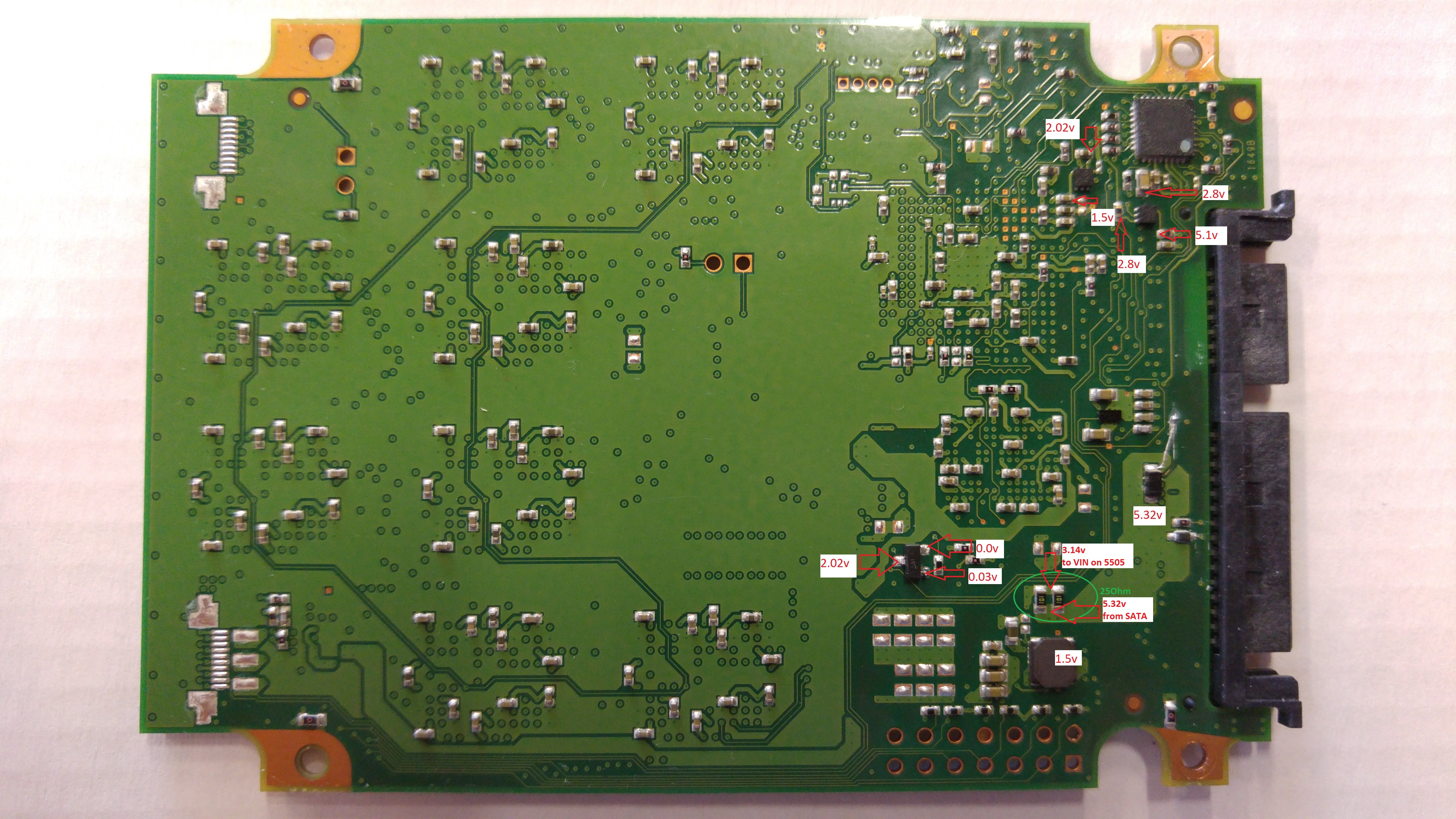
Regulator that have 2.02V is marked with "QY" and another is "NL".
Tryed to replace the "QY" with one from the donor, but nothing changed.
Got mu hands on this drive again.
Regulator that have 2.02V is marked with "QY" and another is "NL".
Tryed to replace the "QY" with one from the donor, but nothing changed.
Re: Crucial MX100 repair after PSU failure
March 12th, 2019, 7:11
The QY device is a 2.5V LDO regulator (TLV70025). The NL device is a 2.8V version of same (TLV70028).
http://www.ti.com/lit/ds/symlink/tlv700.pdf
http://www.ti.com/lit/ds/symlink/tlv700.pdf
Re: Crucial MX100 repair after PSU failure
March 12th, 2019, 8:03
Also what is strange, that 5505 VIN=3.12V and VB=2.4V.
VIN is connected to 5V USB power line trough 25Ohm resistance. On donor board it`s the same connection, but it reaches 5V on VIN pin on 5505.
What can couse this?
VB out goes to ODH voltage regulator input, so it`s undervoltaged and can`t supply correct output voltage to the SPI and others.
VIN is connected to 5V USB power line trough 25Ohm resistance. On donor board it`s the same connection, but it reaches 5V on VIN pin on 5505.
What can couse this?
VB out goes to ODH voltage regulator input, so it`s undervoltaged and can`t supply correct output voltage to the SPI and others.
Re: Crucial MX100 repair after PSU failure
March 12th, 2019, 15:53
Where is this 25 ohm resistance? :? :? :?
Re: Crucial MX100 repair after PSU failure
March 13th, 2019, 4:36
It`s between 5V input from SATA connector and VIN pin on 5505. There is few 100Ohm (market as 101) resistors in parallel. Market them on PCB:
Strange, that I see only 2 100Ohm resistors and it should be 50Ohm, but it measures 25. There shouldn`t be so much voltage drop on 25Ohm. Both ends of resistors measure few MegaOhms to ground, so there is no overcurrent. Is it possible, that under load resistance is increased?
Strange, that I see only 2 100Ohm resistors and it should be 50Ohm, but it measures 25. There shouldn`t be so much voltage drop on 25Ohm. Both ends of resistors measure few MegaOhms to ground, so there is no overcurrent. Is it possible, that under load resistance is increased?
Re: Crucial MX100 repair after PSU failure
March 13th, 2019, 16:31
After posting (and while waiting for premoderation) I found 2 more 100Ohm resistors on other sida of PCB. So there are 4 100Ohm resistors in parallel, that measure 25Ohm.
But still why does it drops voltage down to 3V...
On donor board same voltage input and on both ends I get 5V stable.
Is there anything else on that line? (Sata->VIn on 5505)
But still why does it drops voltage down to 3V...
On donor board same voltage input and on both ends I get 5V stable.
Is there anything else on that line? (Sata->VIn on 5505)
Re: Crucial MX100 repair after PSU failure
March 13th, 2019, 17:26
I would check the Vin voltages at all the regulators and the MSP430.
Re: Crucial MX100 repair after PSU failure
March 14th, 2019, 18:12
Did you measure the voltage on the "storage" capacitor at the 5505?
AIUI, when power is first applied, the 5505 charges its storage capacitor by switching to boost mode. Thereafter, if it senses that the bus capacitor's voltage (5V) has dropped below a power fail threshold, it switches to buck mode and dumps the stored charge back into the circuit to enable the flash controller to process an orderly shutdown.
AIUI, when power is first applied, the 5505 charges its storage capacitor by switching to boost mode. Thereafter, if it senses that the bus capacitor's voltage (5V) has dropped below a power fail threshold, it switches to buck mode and dumps the stored charge back into the circuit to enable the flash controller to process an orderly shutdown.
Re: Crucial MX100 repair after PSU failure
March 15th, 2019, 5:19
Hi!
So MSP430 VIN=2.8V
5505 VIN=3.08V
5505 VB out=2.4V
And updated pisture with voltage regulators input voltages (in green circle).
Storage caps (pin 10 on 5505) measure 3.04V.
So MSP430 VIN=2.8V
5505 VIN=3.08V
5505 VB out=2.4V
And updated pisture with voltage regulators input voltages (in green circle).
Storage caps (pin 10 on 5505) measure 3.04V.
- Attachments
-
Re: Crucial MX100 repair after PSU failure
March 15th, 2019, 19:21
This is my view of the power distribution:
Do you agree? If yes, then ISTM that there are many ICs (and capacitors) which could be responsible for the sag in Vin. Most regulators seem to be able to continue working (0.9V, 1.2V, 1.8V), so these could probably be excluded.
The voltage drop across the 25 ohm equivalent resistor indicates a current draw of 88mA. Clearly this is too high. That said, I confess that I'm surprised at how little current is drawn by these chips, even in this faulty state. :-?
It would be very tempting to see how the SSD behaves if one were to shunt the resistors with 10 ohm, say. It might be risky, though.
Edit: The more I look at those resistors, the less sense they make. :? :? :?
- Code:
                ___          .----.
5V o--+-----+--|___|--+--+---|0.9V|---> Vcore - MCU
      |     |   ___   |  |   |SMPS|
      |     +--|___|--+  |   '----'
TVS   z     |   ___   |  |   .----.
diode A     +--|___|--+  |   |1.8V|
      |     |   ___   |  +---|SMPS|---> SDRAM (NAND, MCU ?)
      |     '--|___|--'  |   '----'
     ===                 |   .----.
     GND      4 x 100R   |   |1.2V|
                         +---|SMPS|---> SDRAM (MCU ?)
                         |   '----'
                         |   .----.
                         |   |2.5V|
                         +---|LDO |---> serial flash
                         |   '----'
                         |   .----.
                         |   |2.8V|
                         +---|LDO |---> MSP430 PMU
                         |   '----'
                         |
                         |   .---------.
                         |   | MP5505  |
                         |   |         |
                         '---|- \    --|---o Storage
                        Vin  |   \     |
                             |    |    |
                             '----|----'
                               VB |
                                  |
                               .------.   .-----.
                               | 3.3V |   | NAND|
                               | SMPS |---|flash|
                               '------'   '-----'
Do you agree? If yes, then ISTM that there are many ICs (and capacitors) which could be responsible for the sag in Vin. Most regulators seem to be able to continue working (0.9V, 1.2V, 1.8V), so these could probably be excluded.
The voltage drop across the 25 ohm equivalent resistor indicates a current draw of 88mA. Clearly this is too high. That said, I confess that I'm surprised at how little current is drawn by these chips, even in this faulty state. :-?
It would be very tempting to see how the SSD behaves if one were to shunt the resistors with 10 ohm, say. It might be risky, though.
Edit: The more I look at those resistors, the less sense they make. :? :? :?
Re: Crucial MX100 repair after PSU failure
March 15th, 2019, 19:42
Is there a load switch which bypasses the resistor network? What are the markings and voltages at the tiny, rectangular IC on the underside of the PCB, nearest the SATA connector and TVS diode?
Re: Crucial MX100 repair after PSU failure
March 15th, 2019, 23:30
Could this be how the 5V power gets past the resistor network? The on/off signal could come from the MSP430 PMU, or it could be controlled via SATA power pin #3 (Power Disable or DevSleep).
- Code:
               on/off
                 |
              .--|--.
              |  _/ |  load switch
            .-|-/  -|-.
            | |     | |
            | '-----' |
            |   ___   |      .----.
5V o--+-----+--|___|--+--+---|0.9V|---> Vcore - MCU
      |     |   ___   |  |   |SMPS|
      |     +--|___|--+  |   '----'
TVS   z     |   ___   |  |   .----.
diode A     +--|___|--+  |   |1.8V|
      |     |   ___   |  +---|SMPS|---> SDRAM (NAND, MCU ?)
      |     '--|___|--'  |   '----'
     ===                 |   .----.
     GND      4 x 100R   |   |1.2V|
                         +---|SMPS|---> SDRAM (MCU ?)
                         |   '----'
                         |   .----.
                         |   |2.5V|
                         +---|LDO |---> serial flash
                         |   '----'
                         |   .----.
                         |   |2.8V|
                         +---|LDO |---> MSP430 PMU
                         |   '----'
                         |
                         |   .---------.
                         |   | MP5505  |
                         |   |         |
                         '---|- \    --|---o Storage
                        Vin  |   \     |
                             |    |    |
                             '----|----'
                               VB |
                                  |
                               .------.   .-----.
                               | 3.3V |   | NAND|
                               | SMPS |---|flash|
                               '------'   '-----'
Re: Crucial MX100 repair after PSU failure
March 19th, 2019, 18:24
In the absence of additional feedback, I offer the following hypothesis.
I believe that the 4 x 100 resistor network provides inrush current limiting, aka "soft start". Designers often implement such a feature by way of an NTC (negative temperature coefficient) resistor, or a fixed resistor shunted by a relay or semiconductor switch (eg SCR).
https://en.wikipedia.org/wiki/Inrush_current_limiter
Fig 2 of the following application note shows NTC resistors (Rt) in a mains rectifier application.
http://www.epcos.com/blob/528070/download/4/pdf-inrushcurrentlimiting-an2.pdf
The following article has examples of inrush current limiting using a fixed resistor and a semiconductor switch:
Power Tips: How to limit inrush current in an AC/DC power supply:
https://e2e.ti.com/blogs_/b/powerhouse/archive/2015/03/31/powertips-how-to-limit-inrush-current-in-an-ac-dc-power-supply
relay bypass circuit
https://e2e.ti.com/cfs-file/__key/communityserver-blogs-components-weblogfiles/00-00-00-03-59/Figure-5_5F00_Input-rectifier-stage-of-PMP10948.jpg
MOSFET bypass circuit
https://e2e.ti.com/cfs-file/__key/communityserver-blogs-components-weblogfiles/00-00-00-03-59/Figure-6_5F00_Update_5F00_Input-stage-of-PMP8920.jpg
In the first case, the NTC resistor may have a resistance of 10 ohms, say, when cold, ie at power-on. This limits the inrush current, especially when there are large capacitors to be charged. The resistor is heated by this current, causing its resistance to very quickly fall to a low value, eg < 1 ohm. The circuit then receives the full supply voltage.
In the second case, the resistor may have a fixed value of 10 ohms, say. After a short delay this resistor is bypassed by either a mechanical (relay) or solid state (MOSFET) switch. As before, the circuit then receives the full supply voltage.
I believe that the MX100 SSD implements inrush current limiting by way of the 4 x 100 resistor network. The MSP430 power management controller monitors the rising voltages and then enables the load switch IC. This switch then bypasses the current limiting network.
WARNING: The following annotated circuits are hypothetical. They may not be accurate.
AIUI, the current MSP430 is not native, ie it came from a different PCB. Therefore the two MSP430 ICs would have different firmware. Perhaps the other PCB did not have a load switch, in which case its MSP430 firmware would not be programmed to control it. In fact there is a trace which runs between the MSP430 and the load switch. I suspect this is the on/off signal, and I'm betting that it is in the off position.
If my hypothesis is correct, then it should be OK to bypass the resistor network with a wire link. Hopefully this is all that is required to recover the data.
Re: Crucial MX100 repair after PSU failure
March 20th, 2019, 8:57
Hi!
Thank you so much for your effort and time.
I have updated picture with margins on that 2 chips.
25211 seems to be CSD25211W1015, which is switching mosfet. It is sitting also on 5V rail from SATA in parallel with this 25Ohm resistance. So Iˇm thinking, that soft start theory could be correct. Also donor board has absolutely same 5V input (through 25Ohm resistor in parallel with mosfet).
But I was unable to find datasheet for second chip - 48H6ZI.
Update: while inspecting 25211 area found one more problem, got it under microscope on picture. Fortunally have spare 25211 from donor. Will give resnond after changing chip and repairing trace.
- Attachments
-
-
-
Re: Crucial MX100 repair after PSU failure
March 20th, 2019, 9:30
I wonder, was it necessary to replace the MPS430 chip... Maybe will have to return the original back, if repairing trace and replacing 25211 willn't give result...?
Any chance that MSP430 is good and didn't got damaged while putting wrong voltage in?
Any chance that MSP430 is good and didn't got damaged while putting wrong voltage in?
Re: Crucial MX100 repair after PSU failure
March 20th, 2019, 15:42
ISTM that it should be OK to bridge the resistor network with a wire link. If the SSD then powers up, I would try applying a firmware update (after first recovering your data). Hopefully this firmware update will also update the code in the MSP430.
BTW, here is an alternative consideration:
Power Disable Feature (SATA 3.2+ / 3.3):
http://www.hddoracle.com/viewtopic.php?f=46&t=2094
Load switches (Devslp):
http://www.hddoracle.com/viewtopic.php?f=100&t=1615&p=16092#p16092
BTW, here is an alternative consideration:
Power Disable Feature (SATA 3.2+ / 3.3):
http://www.hddoracle.com/viewtopic.php?f=46&t=2094
Load switches (Devslp):
http://www.hddoracle.com/viewtopic.php?f=100&t=1615&p=16092#p16092
Powered by phpBB © phpBB Group.